


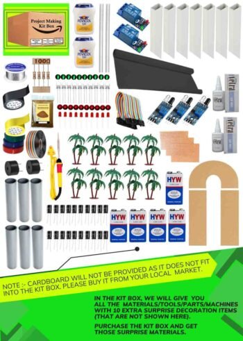
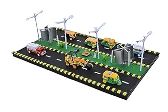
Footstep Power Generation Science Project Kit For School & Engineering Students

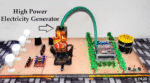
Footstep Power Generate Mechanical Project
Generate Electricity From Mechanical Energy
Generate Electricity By Pressure
Generate Electricity By Walking
Footstep Power Generate Project
Terms & Conditions: Our project kits are designed for educational and demonstration purposes only. The projects created using these kits represent prototype ideas and concepts. They are not ready-to-use real-life products. To use any project in real-world applications, further research, development, and testing may be required. By purchasing this kit, the buyer agrees that the project is intended only for learning and experimental use.
Original price was: ₹4,499.00.₹3,300.00Current price is: ₹3,300.00.
These days as a result of increasing population we are facing many issues of electricity. As we create renewable energy from non-renewable energy, like from solar energy and wind energy. Solar energy comes with a condition, like it creates energy only in the presence of sun rays, it requires heat to generate kinetic energy and same with wind energy it requires wind to be blown all the time to generate kinetic energy.
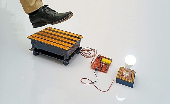
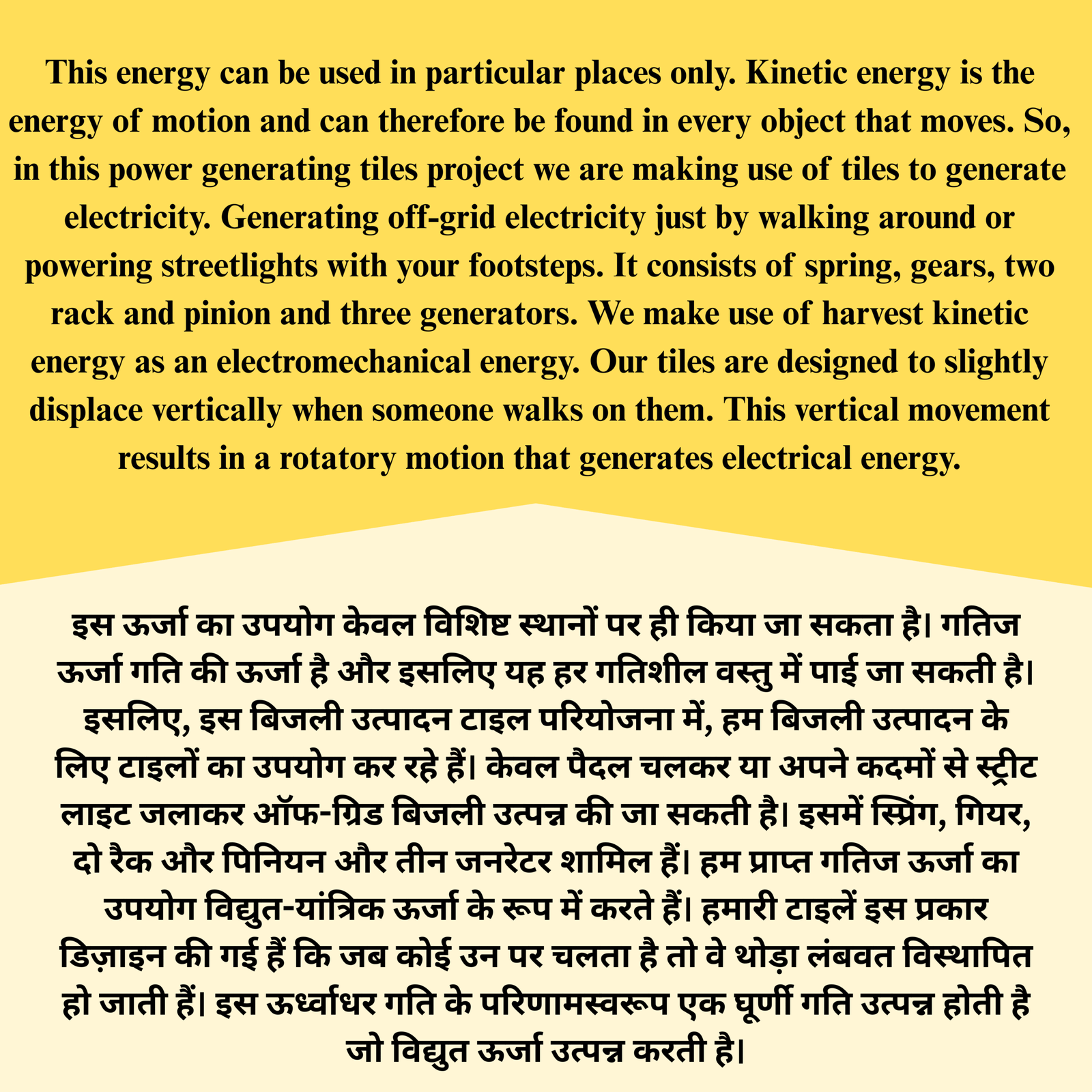
This energy can be used in particular places only. Kinetic energy is the energy of motion and can therefore be found in every object that moves. So, in this power generating tiles project we are making use of tiles to generate electricity. Generating off-grid electricity just by walking around or powering streetlights with your footsteps. It co…
Terms & Conditions: Our project kits are designed for educational and demonstration purposes only. The projects created using these kits represent prototype ideas and concepts. They are not ready-to-use real-life products. To use any project in real-world applications, further research, development, and testing may be required. By purchasing this kit, the buyer agrees that the project is intended only for learning and experimental use.
Related Products

Introduction Of Project In This Project We show when vehicle cross the rood then breaker move and generate electricity ( here we convert mechanical power to electrical power ) so when electricity generate that electricity we store in battery and when night start that time that store power automatic go to street light and street light glowing so in this project we show how to generate electricity by speed breaker , If You Want to Only Watch Full Making Video Of Project Step by Step With Project File and Synopsis file.
Terms & Conditions: Our project kits are designed for educational and demonstration purposes only. The projects created using these kits represent prototype ideas and concepts. They are not ready-to-use real-life products. To use any project in real-world applications, further research, development, and testing may be required. By purchasing this kit, the buyer agrees that the project is intended only for learning and experimental use.
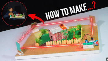
How It Works: Laser Beam Setup: A laser torch emits a beam that travels across the area by reflecting off three strategically placed mirrors (glasses). This configuration creates a continuous laser barrier around the perimeter of a model house or any area you wish to secure.
LDR Detection: The laser beam ultimately hits an LDR module, which is sensitive to light. As long as the laser beam is unbroken and falls on the LDR, the system remains in a passive state, with no alarm triggered.
Relay and Buzzer Activation: The LDR is connected to a single-channel relay module that controls a 9V buzzer. If the laser beam is interrupted, the LDR detects a change in light intensity, signaling the relay to activate the buzzer. This results in an audible alarm that warns you of the potential intrusion.
Unauthorized Entry Alert: The alarm is designed to activate whenever there is an obstruction in the laser path, such as someone entering the secured area without permission. This feature provides a simple yet effective means of safeguarding your space.
Terms & Conditions: Our project kits are designed for educational and demonstration purposes only. The projects created using these kits represent prototype ideas and concepts. They are not ready-to-use real-life products. To use any project in real-world applications, further research, development, and testing may be required. By purchasing this kit, the buyer agrees that the project is intended only for learning and experimental use.


In this video, I demonstrate how to create a floating house using ACC blocks (Autoclaved Aerated Concrete blocks) and a cardboard house. I built the base of the house with ACC blocks, which are lightweight and float on water. When placed in a water tank, the house’s height automatically rises with the water level, preventing it from sinking. This project shows how real-life houses can be designed to stay afloat during heavy rainfall or floods, offering a solution for disaster management in flood-prone areas. The idea behind this floating house concept is to build homes that automatically adjust their height based on the rising water levels, ensuring that they do not get submerged during extreme weather conditions.
This floating house project is a great idea for those interested in science experiments, civil engineering projects, or innovative disaster management solutions. Whether you’re a student, a science enthusiast, or someone looking for unique school projects, this video will help you understand the concept of a floating house and its potential use in real life. Watch the full video to see how you can make this project at home and learn about flood-resistant house designs.
Terms & Conditions: Our project kits are designed for educational and demonstration purposes only. The projects created using these kits represent prototype ideas and concepts. They are not ready-to-use real-life products. To use any project in real-world applications, further research, development, and testing may be required. By purchasing this kit, the buyer agrees that the project is intended only for learning and experimental use.

IR Sensor: The IR sensor is used to detect the presence of a vehicle. When a vehicle enters the range of the sensor, it detects its presence. Relay Module: The relay module is used to control the system. Once the IR sensor detects a vehicle, it sends a signal to the relay module, which in turn activates the LED bulb and alarm. LED Bulb: The LED bulb is used to indicate the presence of a vehicle coming from the opposite side. When a vehicle is detected by the IR sensor, the LED bulb on the other side turns on, alerting drivers. Alarm: The alarm sounds to provide a warning of the vehicle’s approach, ensuring further attention and safety. Wiring and Connections:
Working Principle: When a vehicle enters the range of the IR sensor, the sensor detects its presence. The IR sensor sends a signal to the relay module. The relay module then activates the LED bulb and alarm on the opposite side. The alarm and LED bulb warn the drivers that a vehicle is approaching.
Objectives: Enhance road safety by alerting drivers about vehicles approaching from the opposite side. Prevent traffic accidents, especially in areas with limited visibility. Create a simple and cost-effective vehicle detection system for traffic monitoring.
Expected Outcomes: Early warning system for approaching vehicles, giving drivers more time to react. Improved awareness and timely responses from drivers to avoid accidents. Efficient use of sensors and alarms to ensure smooth traffic flow and safety.
Applications: Safety alert system on narrow roads or blind spots. Traffic control at signal points or crossing areas. Monitoring vehicles in industrial areas or warehouses where safety is critical.
Future Improvements: Use of advanced sensors (e.g., ultrasonic) for better accuracy. Integration with traffic signal systems for automated control. Solar-powered systems for cost-effective outdoor applications.
Terms & Conditions: Our project kits are designed for educational and demonstration purposes only. The projects created using these kits represent prototype ideas and concepts. They are not ready-to-use real-life products. To use any project in real-world applications, further research, development, and testing may be required. By purchasing this kit, the buyer agrees that the project is intended only for learning and experimental use.
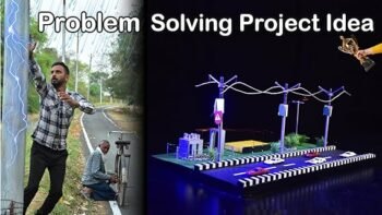
The Problem: Electrical poles, being integral components of power distribution networks, are susceptible to various faults, including short circuits. These faults pose significant dangers to both nearby individuals and the infrastructure itself. However, identifying when a pole is experiencing a fault, especially during adverse weather conditions like rain, can be challenging.
The Solution: Our project introduces a visual indicator system designed to promptly notify observers when a fault occurs in an electrical pole. This system consists of a small strip affixed to the pole, divided into two distinct colors: green and red. During normal operating conditions, when no fault is present, the strip remains green, indicating that the pole is functioning safely. However, when a fault such as a short circuit occurs, the strip promptly changes its color from green to red, si
How it Works: The indicator strip is equipped with sensors capable of detecting abnormal electrical activity, such as an increase in current flow due to a short circuit. Upon detecting such an anomaly, the sensor triggers the color change mechanism, causing the strip to transition from green to red. This visual change serves as an immediate warning sign to anyone in the vicinity that the pole is experiencing a fault and should be avoided.
Benefits: Enhanced Safety: By providing a clear visual indication of faults, the system helps prevent accidents and injuries caused by inadvertent contact with electrified poles. Timely Response: Prompt identification of faults enables swift corrective action, minimizing downtime and potential damage to the electrical infrastructure. User-Friendly: The simplicity of the color-changing indicator strip ensures that it is easily understandable by individuals of all backgrounds and levels of expert
Terms & Conditions: Our project kits are designed for educational and demonstration purposes only. The projects created using these kits represent prototype ideas and concepts. They are not ready-to-use real-life products. To use any project in real-world applications, further research, development, and testing may be required. By purchasing this kit, the buyer agrees that the project is intended only for learning and experimental use.


Generate Electricity By Waste Materials
Generate Electricity By Plastic
Free Energy Generate Project
electricity from garbage
Waste Materials By Generate Electricity
Terms & Conditions: Our project kits are designed for educational and demonstration purposes only. The projects created using these kits represent prototype ideas and concepts. They are not ready-to-use real-life products. To use any project in real-world applications, further research, development, and testing may be required. By purchasing this kit, the buyer agrees that the project is intended only for learning and experimental use.
Design and Operation: VAWTs typically consist of two or more blades that rotate around a vertical axis. The blades can have different shapes, such as straight, helical, or S-shaped, and are attached to a central shaft. As the wind blows, the blades capture the kinetic energy and convert it into mechanical rotation, which can then be used to generate electricity through a generator or to perform other tasks directly.
Terms & Conditions: Our project kits are designed for educational and demonstration purposes only. The projects created using these kits represent prototype ideas and concepts. They are not ready-to-use real-life products. To use any project in real-world applications, further research, development, and testing may be required. By purchasing this kit, the buyer agrees that the project is intended only for learning and experimental use.

Terms & Conditions: Our project kits are designed for educational and demonstration purposes only. The projects created using these kits represent prototype ideas and concepts. They are not ready-to-use real-life products. To use any project in real-world applications, further research, development, and testing may be required. By purchasing this kit, the buyer agrees that the project is intended only for learning and experimental use.
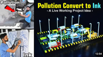
Objective: To mitigate air pollution by capturing vehicle emissions and converting them into usable ink.
Technology Used: Carbon filters integrated into vehicles to capture emitted smoke particles.
Conversion Process: Smoke particles trapped by filters are processed to extract carbon-based materials suitable for ink production.
Terms & Conditions: Our project kits are designed for educational and demonstration purposes only. The projects created using these kits represent prototype ideas and concepts. They are not ready-to-use real-life products. To use any project in real-world applications, further research, development, and testing may be required. By purchasing this kit, the buyer agrees that the project is intended only for learning and experimental use.
Solar Street Light School Science Project
Solar Street Light Project
LDR Solar Street Light
Automatic On/Off Solar Street Light
Automatic Solar Street Light School Science Project
Terms & Conditions: Our project kits are designed for educational and demonstration purposes only. The projects created using these kits represent prototype ideas and concepts. They are not ready-to-use real-life products. To use any project in real-world applications, further research, development, and testing may be required. By purchasing this kit, the buyer agrees that the project is intended only for learning and experimental use.
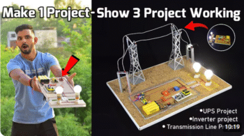
Welcome to our Smart Inverter Project tutorial! In this video, we’ll show you how to build a DIY inverter that provides an automatic power backup solution for your home. If you’re looking for a continuous power supply during outages, this inverter with battery storage will keep your lights on even when the main power goes out.
This project involves creating a smart inverter circuit that can seamlessly switch from AC power to a 12V DC battery when the electricity supply is interrupted. Not only does it ensure uninterrupted power to your 230V AC appliances, but it also recharges the battery when the main power is available.
In this detailed how-to guide, we cover everything from the basic components needed to the step-by-step assembly and testing of the inverter. Plus, we’ll discuss how this inverter system can be adapted for use in transmission lines, ensuring a reliable power supply to cities from substations, even if the main transmission line fails temporarily.
What You’ll Learn in This Video:
Inverter Basics: Understand how an inverter works and the role of battery storage in providing continuous power.
Step-by-Step Construction: Follow our easy instructions to build your own inverter circuit with a 12V DC battery backup.
Automatic Switching: Learn how the inverter automatically switches to battery power during outages and back to AC power when available.
Practical Applications: Discover how this smart inverter system can be used in transmission lines to maintain city power supply during disruptions.
Terms & Conditions: Our project kits are designed for educational and demonstration purposes only. The projects created using these kits represent prototype ideas and concepts. They are not ready-to-use real-life products. To use any project in real-world applications, further research, development, and testing may be required. By purchasing this kit, the buyer agrees that the project is intended only for learning and experimental use.
Reviews
There are no reviews yet.