


Bluetooth Controlled Car Using Arduino Uno Engineering Final Year Arduino Project

The Arduino-based Mobile Control Bluetooth Robotic Car is an innovative project designed to demonstrate how Bluetooth can be used for smart navigation. This car can be seamlessly driven, left, right, forward, and backward using your mobile phone.
Original price was: ₹3,999.00.₹3,000.00Current price is: ₹3,000.00.
The Arduino-Based Mobile Controlled Bluetooth Robotic Car is an innovative and educational robotics project designed for students, hobbyists, and tech enthusiasts. This project demonstrates how wireless communication can be integrated with embedded systems to create a smart and efficient robotic vehicle.
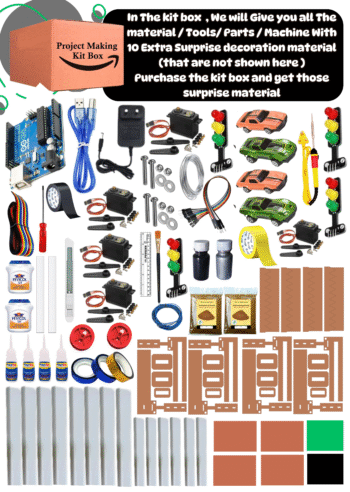
The car is powered by an Arduino Uno microcontroller, which acts as the brain of the system. It receives real-time commands via Bluetooth technology from a smartphone, allowing the user to control the movement of the car — forward, backward, left, right, and stop — with just a few taps on a mobile app (such as the Bluetooth Controller app).
This project showcases the seamless integration of Bluetooth HC-05 module, L293D motor driver, DC motors, and Arduino Uno, offering a clear understanding of wireless control, motor interfacing, and automation principles.
It is ideal for engineering students, DIY enthusiasts, and beginners in robotics who want to explore IoT and Bluetooth communication in embedded systems. The project can also be upgraded with ultrasonic sensors, line-following capabilities, or voice command control for advanced functionality.
By building this project, learners gain valuable hands-on experience in circuit design, Arduino programming, and real-time Bluetooth interfacing, making it a perfect project for academic exhibitions, robotics competitions, and final-year engineering submissions.
Related Products


Transmission Line Fault Detection Project
Electrical Engineering Project Making Kit Box
Fault Detection In Transmission Line Project
Line To Ground Fault Detection
Three Phase Transmission Line Fault Detection Project
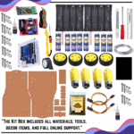
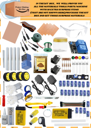
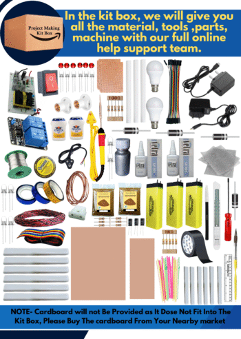
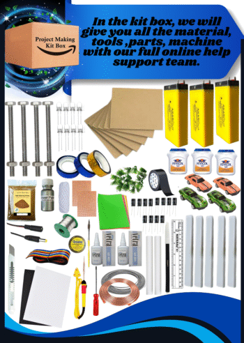
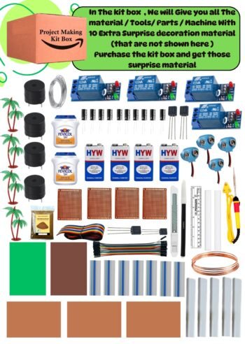
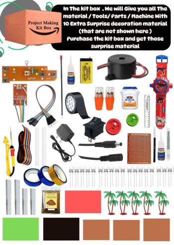
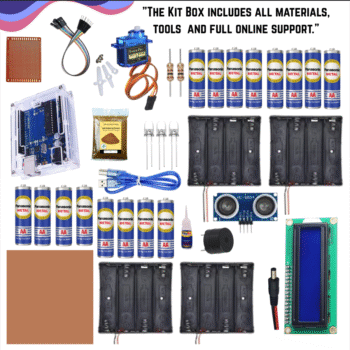
In This Project Kit Box We will Give You Only All Components And Parts And Extra Decoration Materials And Step By Step Videos 3D Circuit Diagram And Reading Pages With Synopsis File And Online Training Access

The Purpose of making this project is to generate electrical energy from bad materials like plastic, rubber, garbage and bad stuff etc. and store that electrical energy in the battery through the circuit and use that electrical energy to operate the whole project. And the LED bulb is shown to be turned on , In This Project when burning start then heating generate and heating penal start converting heat to electricity and that electricity we can see on multi meter display , we can see how much voltage generate by waste materials and we electricity generating perfectly then automatic heating sensor on the output power supply then Big LED Bub start glowing and our idea everyone can see in live working , Our Idea 100% work for generate electricity by waste materials . So this is our best live working idea

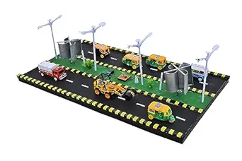
In this project, you will see a 4-way traffic light control system with an advanced safety feature – traffic spikes/barriers. When the signal is red, the spikes stay up to stop vehicles from breaking rules. If anyone tries to cross, their vehicle can get a flat tyre. 🚗❌ When the light turns green, the spikes go down, and vehicles can move safely.
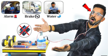
It has been shown in this project that if the driver tries to sleep, as soon as he closes his eyes for more than 3 seconds, an alarm will start ringing which will make him open his eyes and if he still does not open his eyes, after that driver vehicle automatic stop and water will splash on his face which will open his eyes and then he will not try to sleep again.

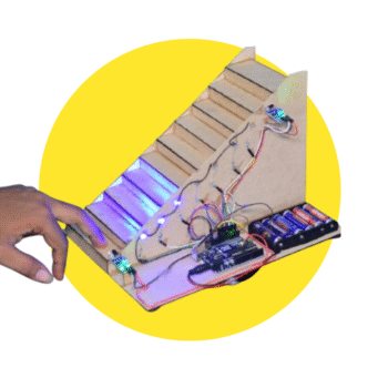
The Automatic Staircase Lighting System is an Arduino-based project that uses IR sensors to detect movement and control LED lights automatically. When a person steps on the first or last stair, the lights turn on and switch off after crossing, saving energy and enhancing safety. Ideal for homes, malls, parks, and public places.
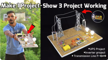
Welcome to our Smart Inverter Project tutorial! In this video, we’ll show you how to build a DIY inverter that provides an automatic power backup solution for your home. If you’re looking for a continuous power supply during outages, this inverter with battery storage will keep your lights on even when the main power goes out.
This project involves creating a smart inverter circuit that can seamlessly switch from AC power to a 12V DC battery when the electricity supply is interrupted. Not only does it ensure uninterrupted power to your 230V AC appliances, but it also recharges the battery when the main power is available.
In this detailed how-to guide, we cover everything from the basic components needed to the step-by-step assembly and testing of the inverter. Plus, we’ll discuss how this inverter system can be adapted for use in transmission lines, ensuring a reliable power supply to cities from substations, even if the main transmission line fails temporarily.
What You’ll Learn in This Video:
Inverter Basics: Understand how an inverter works and the role of battery storage in providing continuous power.
Step-by-Step Construction: Follow our easy instructions to build your own inverter circuit with a 12V DC battery backup.
Automatic Switching: Learn how the inverter automatically switches to battery power during outages and back to AC power when available.
Practical Applications: Discover how this smart inverter system can be used in transmission lines to maintain city power supply during disruptions.

The Problem: Electrical poles, being integral components of power distribution networks, are susceptible to various faults, including short circuits. These faults pose significant dangers to both nearby individuals and the infrastructure itself. However, identifying when a pole is experiencing a fault, especially during adverse weather conditions like rain, can be challenging.
The Solution: Our project introduces a visual indicator system designed to promptly notify observers when a fault occurs in an electrical pole. This system consists of a small strip affixed to the pole, divided into two distinct colors: green and red. During normal operating conditions, when no fault is present, the strip remains green, indicating that the pole is functioning safely. However, when a fault such as a short circuit occurs, the strip promptly changes its color from green to red, si
How it Works: The indicator strip is equipped with sensors capable of detecting abnormal electrical activity, such as an increase in current flow due to a short circuit. Upon detecting such an anomaly, the sensor triggers the color change mechanism, causing the strip to transition from green to red. This visual change serves as an immediate warning sign to anyone in the vicinity that the pole is experiencing a fault and should be avoided.
Benefits: Enhanced Safety: By providing a clear visual indication of faults, the system helps prevent accidents and injuries caused by inadvertent contact with electrified poles. Timely Response: Prompt identification of faults enables swift corrective action, minimizing downtime and potential damage to the electrical infrastructure. User-Friendly: The simplicity of the color-changing indicator strip ensures that it is easily understandable by individuals of all backgrounds and levels of expert

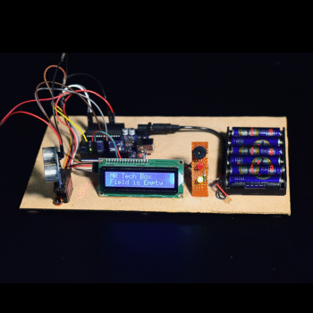
In this project kit box we will give you all components and parts , Extra decoration materials , How to make full step by step video and 3D circuit diagram , Reading pages , Synopsis file , Online training access There will be more wires around the field wall , The direction from which the animals are entering the fields, then on coming in touch with the wire which is around, the alarm will start sounding from the same direction, so that the animal will feel that someone is coming and he will run away due to which the farmer is not in the fields. There will be safety and there will be no harm to the farms and animals. So If farmer go to out side of field then his crop save by animal Best Part Of This Project , It’s System Making Cost Very Low Any Farmer Can buy or Make Himself And Use In Field .

This Idea For Safety Gadgets for Students , If any student have problem and he want to inform his home then he press his watch switch and his home alert alarm start , This is best Innovative idea and easily making base if any students make this project for his science Exhibition , This is Best inspire award project idea and This Idea not available on YouTube , So This is Unavailable Idea On YouTube For Inspire Award Project
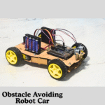
This project is based on an Object Detection Radar System which uses an Ultrasonic Sensor mounted on a Servo Motor controlled by an Arduino Uno. The servo motor continuously rotates from 0° to 180° to scan the surroundings, similar to a radar system. When any object comes within the sensing range (40 cm), the ultrasonic sensor detects it, and the servo motor immediately stops at that specific angle. The system then displays the detected object’s distance and angle on the I2C Display.

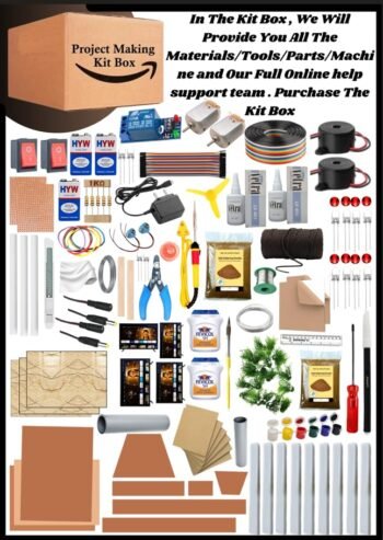
I will Provide You All Components Parts Machine Tools And Decoration Materials Available In Kit Box .I will Provide You Full Step By Step Making Video with 3D Cicuit Diagram , Report File , Synopsis File , PPT

Design and Operation: VAWTs typically consist of two or more blades that rotate around a vertical axis. The blades can have different shapes, such as straight, helical, or S-shaped, and are attached to a central shaft. As the wind blows, the blades capture the kinetic energy and convert it into mechanical rotation, which can then be used to generate electricity through a generator or to perform other tasks directly.
Reviews
There are no reviews yet.